Built-in Bluetooth
The SmartSolar MPPT chargers can be controlled and configured over Bluetooth from the VictronConnect app. This makes it possible to set up the unit, manage it and obtain data at a glance — for example battery voltage and current, PV voltage and current, and historical data. With the BlueSolar version, an optional Bluetooth dongle is required.
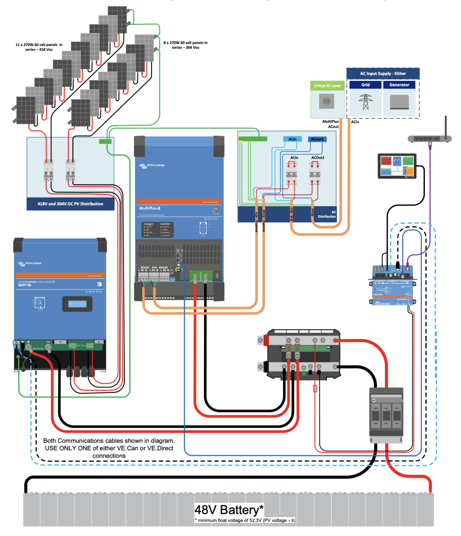
Maximum PV array power as a function of system voltage
| | PV power for a 48 V battery voltage |
|---|
| MPPT 450/100 (100 A) | 5800 Wp |
| MPPT 450/200 (200 A) | 11500 Wp |
Several independent MPPT tracking inputs
The SmartSolar RS units are fitted with two (450/100) and four (450/200) MPPT trackers (20 A, Isc, per tracker), for maximum yield at your specific location.
Outstanding conversion efficiency
Fan cooling. Maximum efficiency of 96%. Full output current up to 40°C.
Flexible charge algorithm
Fully programmable charge algorithm, and eight pre-programmed algorithms that can be selected with a rotary switch.

Ultra-fast Maximum Power Point Tracking (MPPT)
Especially in cloudy conditions, when light intensity changes constantly, an ultra-fast MPPT controller will improve energy harvest by up to 30% compared with PWM (pulse-width modulation) charge controllers, and by up to 10% compared with slower MPPT controllers.
Advanced Maximum Power Point detection in case of partial shading
In partial shading conditions, two or more maximum power points may be present on the voltage-power curve. Conventional MPPTs tend to lock onto a local MPP, which may not be the optimal MPP. The innovative SmartSolar algorithm will always maximise energy harvest by locking onto the optimal MPP.
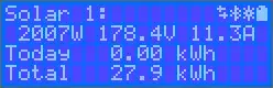
Built-in LCD display
The display reads the parameters of the battery and the controller. The same parameters are accessible from a smartphone or a device with an active Bluetooth function. In addition, the Bluetooth function can also be used to configure the system and change the settings using VictronConnect.
Programmable relay
It can be programmed (among other things with a smartphone) to trigger an alarm or other events.

Remote monitoring and control
When combined with a GX device (for example a Cerbo GX), you can monitor and control your MPPT charge controller and your system either locally (LAN) or remotely over the internet from anywhere in the world, through the free VRM app and the free VRM website. You can access it from a phone, tablet, laptop or PC running various operating systems. The level of control over your system is unlimited, whether to adjust settings on your Multi or to start your back-up generator automatically, and much more.
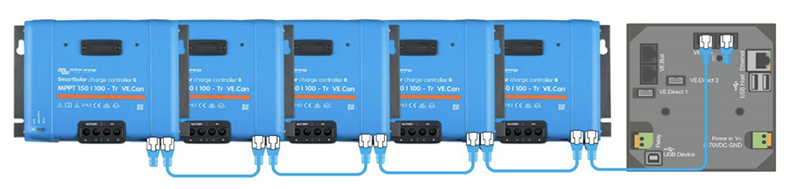
Built-in VE.Can
The SmartSolar solar chargers with VE.Can are fitted with 2 CAN bus ports. They allow communication with other SmartSolar solar chargers that are also fitted with RJ45 CAN bus ports. The additional MPPTs are simply connected in series to each other with a plain RJ45 cable.
In this way, all the SmartSolar VE.Can chargers will synchronise according to their charge stages. They can also send their data, through a plain RJ45 cable, to a GX supervision device.
Thanks to VE.Can, up to 25 charge controllers can be installed in parallel. Each controller can be supervised individually from a Color Control GX or Cerbo GX device, from the VRM web portal or from a smartphone over Bluetooth.
The CAN bus is not galvanically isolated on this charger. The CAN bus is connected to the negative-pole connection of the battery. The CAN bus interface will be referenced to ground if the negative pole of the battery is earthed. In the case of a system with positive grounding, a CAN isolation module will be required to connect the CAN bus interface to ground. To provide maximum flexibility, the battery voltage is used for the V+ supply line of the VE.Can. This means that all the equipment connected to the VE.Can represents a permanent load on the battery.
One end of a CAN cable must be fitted with a bus terminator. This is done by inserting a bus terminator into one of the two RJ45 connectors and the CAN cable into the other. In the case of a node (two CAN cables, one on each RJ45 connector), no terminator is required.